Back

Ex 6A: Gassing up of cargo tanks and operations of related system Part 1

Function: Replacement of inert gas in cargo tanks with LNG vapour

The purpose of gassing-up cargo tanks is to remove the inert gas contained within the cargo tanks because inert gas contains approximately 15% carbon dioxide which will freeze at approximately -60°C and produce a white powder that can block valves, filters, and nozzles.

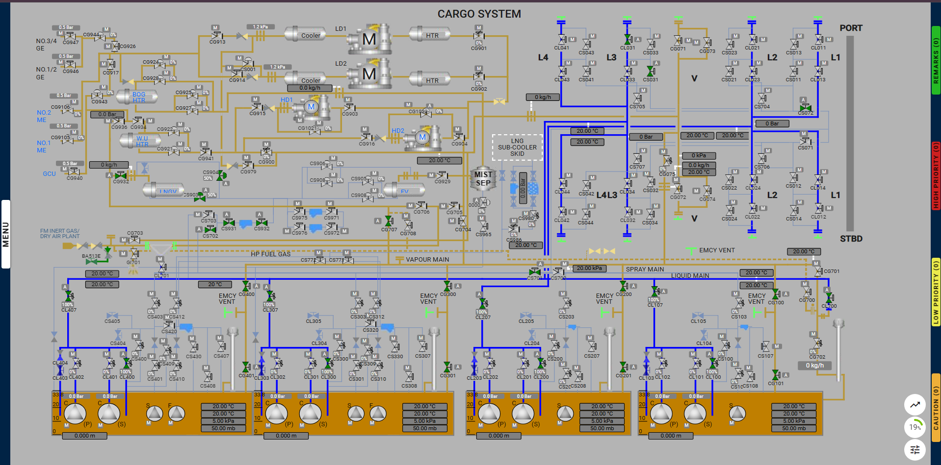
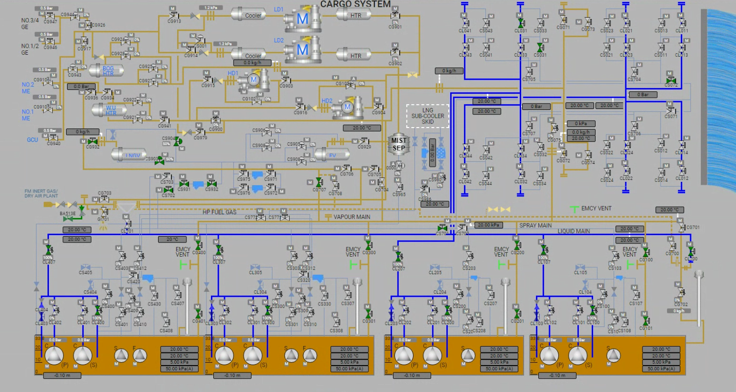
LNG liquid is supplied from the terminal to the liquid manifold where it passes to the spray line via an ESD liquid manifold valve to the vessel’s LNG vaporizer. It is then delivered as LNG vapor into the top of the cargo tanks via the vapor line and exits from the cargo tank via the filling lines. From here it can be vented to the atmosphere via the No.1 vent mast for step one of the process. Step two then follows with the LNG vapor being returned to the terminal using a high-duty (HD) compressor.

In some instances venting to the atmosphere is not permitted so options available include sending the vapor to the terminal, using the vapor as a gas fuel supply for the generator engines, or sending it for gas burning in the Gas Combustion Unit (GCU); or a combination of these choices.

It should be noted that the level of methane vented into the atmosphere is dependent upon the terminal regulations, which should be discussed and agreed upon before operations commence.

Performance criteria

  • 1st step methane 5% No.1 vent mast
  • 2nd step cargo tanks bottom methane content >99%
  • 2nd step cargo tanks carbon dioxide content <1% in volume

Auxiliaries involved

  • LNG vaporizer
  • High duty compressor

Operation duration

  • Steps 1 and 2: 20 hours, volume change ratio 1.7 times

Necessary device

  • Portable methane analyzer
  • Portable carbon dioxide meter

Checkpoints

  • Sampling points and sampling lines in the cargo tanks
  • No.1 vent mast

This exercise is carried out onboard an LNG carrier, where liquid LNG is provided by the shore and converted into vapor using onboard LNG vaporizer equipment. The LNG vapor is then introduced into the cargo tanks from the top, replacing the heavier inert gas present inside the tanks. The inert gas is extracted from the bottom of the tank and released into the atmosphere.

The exercise is divided into two main steps:

  1. Step 1: Release of inert gas to the atmosphere.
  2. Step 2: Once the LNG vapor is sufficiently present, it cannot be released into the atmosphere. Instead, it is sent to shore via the HD compressor onboard the LNG carrier.

Exercise Overview:

  1. Prerequisites and Setup:

Setting up the correct configuration of emergency shutdown systems. Starting the manifold water curtain. Preparing gas measurement instruments for use. Preparing the LNG vaporizer. Opening the required valves and connecting the necessary hoses (or “spool pieces”).

  1. Assessment Process:

The assessment begins when the actual flow of LNG starts from the shore. The user must ensure the following during the assessment:

  • The vapor flow is maintained between 11,500 to 12,500 m³ per hour.
  • The LNG vapor outlet temperature reaches 40°C.
  • All gas sampling points are monitored to assess the current atmosphere status.
  1. Part 1 Completion: The first part of the exercise is completed when the LNG vapor properties are visible on the gas detectors, confirming the proper replacement of Inert gas by LNG vapor inside the tank.
  2. Part 2: HD Compressor Operation: The second part of the exercise involves preparing the HD compressor and generators for use. The user must ensure the correct lineup by opening the required valves and connecting the necessary hoses. Once the HD compressor is started, the warming-up process begins as part of the assessment.
  • During this phase, the user must continuously monitor the tank pressure, ensuring it remains between 7 kPa and 18 kPa throughout the process.
  1. Completion Criteria:
  • The exercise is considered complete once the tank pressure is correctly maintained within the specified range.
  • The user is assessed based on how well they respond to various remarks, questions, and alarms that arise during the exercise.

Line up for the Gassing up Step 1:

Learning Objectives for the Exercise

Participants will be able to effectively demonstrate the process of gassing up cargo tanks on LNG ships, understanding the safety protocols, operational procedures, and the significance of maintaining safe vapor conditions.

Key Components:

Understanding Gassing Up:

  • Explain the purpose of gassing up cargo tanks to prepare them for loading LNG.
  • Identify the importance of creating a safe vapor environment and managing temperature and pressure.

Operational Procedures:

Detail the step-by-step process for gassing up cargo tanks, including:

  • Preparation and inspection of gassing equipment.
  • Connection of vapor lines to the cargo tanks.
  • Control of gas flow rates and monitoring pressure during the operation.

Monitoring and Verification:

  • Demonstrate the use of pressure gauges and gas analyzers to monitor the gassing up process.
  • Describe how to confirm that vapor conditions are within safe operational limits.

Practical Demonstration:

  • Simulate the gassing up process in a controlled environment or through hands-on training exercises.
  • Role-play scenarios to address potential challenges or deviations from the procedure.

Assessment Criteria:

  • Ability to articulate the significance of gassing up cargo tanks.
  • Accurate execution of the gassing up procedure and effective monitoring.

By achieving this objective, participants will acquire the knowledge and skills necessary for safely and efficiently gassing up cargo tanks on LNG ships, ensuring safe and effective operations.

Milestones

  • Learning and Training Phase – Pre-Requisites for the start of operation:
  1. Configure the Correct Setting for the ESD.
  2. Start the Manifold Water Curtain.
  3. Prepare Gas Instruments for Use.
  4. Prepare LNG Vaporizer for Use.
  5. Connect Manifold Arm Spool Piece.
  6. Open Required Valves for Line-Up and Connect Spool Pieces.


  • Assessment Phase – Operational flow and Assessment:
  1. Start Gassing-Up with Minimum Flow of 10m³/h.
  2. Achieve 40°C in LNG Vaporizer Outlet Temperature.
  3. Check All Gas Sampling Points.
  4. Monitor Vapour Outlet No.1 Vent.

Actions taken during the exercise

Deviation from Exercise

  • After starting or resuming the cooldown, the user must not open any non-required valves or close any required valves. If this happens, a caution message will appear, instructing the user to undo the previous action.
  • If the user fails to correct the action, the exercise will be terminated.

Not Maintaining the Inlet and Outlet Flow

  • The user must ensure that the LNG vaporizer outlet flow and vapor to atmosphere flow are maintained between 11,500 m³/h and 12,500 m³/h.
  • If the flow deviates from this range, alarms will be triggered, with a high-priority alarm issued if the issue persists.
  • If the user cannot restore the flow, the exercise will be terminated within one minute.

Note: To maintain the LNG vaporizer outlet flow, adjust Valve CS903 in combination with the Flow from Shore and
to maintain the vapor-to-atmosphere flow, adjust Valve CG702 as needed.

Not Opening the Warm-Up Heater Bypass Valve

  • During the initial phase of the exercise, the user will be prompted to open the outlet bypass valve of the LNG vaporizer.
  • If the valve is not opened within 15 seconds, an LAHH alarm will be triggered.
  • The user will have one minute to open the valve. If the valve is not opened in time, the exercise will be terminated.


Alarms & Remarks

Alarm Condition Alarm Time Alarm Level Alarm Title Alarm Description Action
remark Preparing Of LNG Vaporizer Usually, the LNG vaporizer is properly prepared 3 hours before the operation.
remark Increase LNG Flow rate Vapor blocks might be there inside the lines, increasing the LNG flow rate from shore to 15 m³/h.
remark Open LNG Vaporizer Bypass valve Open the LNG Vapourizer Bypass valve immediately.
remark Open The Gas Detector Open the gas detector sampling point on the liquid line in any of the 4 tanks.
remark Increase LNG Vaporizer Outlet Temperature Increase the outlet temperature of the LNG Vaporizer to 40°C.
remark Valve CS904 To Auto Mode Set the valve output value to 40 and change the valve to auto mode.
caution Maintain LNG Vaporizer Outlet Vapour Maintain the LNG vaporizer outlet vapor flow between 5000 kg/h to 6750 kg/h.
caution Maintain LNG Vaporizer Flow And Vapour Flow To Atmosphere Maintain LNG vaporizer outlet flow and vapor flow to the atmosphere between 11500 kg/h to 12500 kg/h.
caution Deviation Detected Deviation from the exercise is detected, undo your last action.

Step-by-Step Procedure.

  • Learning and Training Phase – Pre-Requisites for the start of operation:

1 – Configure the Correct Setting for the ESD

  1. Set the Ship/Shore Link Selector Switch to Use.
  2. Set the Pneumatic Selector Switch to Bypass.
  3. Set the ESD Port Selector Switch to Loading.
  4. Set the ESD Mode Switch to Normal.

2 – Start the Manifold Water Curtain

  • To start the water curtain, go to the Miscellaneous Equipment page and activate either the bilge pumps or the fuel gas pumps. This will activate the water curtain.

3 – Prepare Gas Instruments for Use

  • To start the gas instruments, go to the Miscellaneous Equipment page and activate the portable multi-gas detector by holding the power button for 5 seconds.

4 – Prepare LNG Vaporizer for Use

  • Open both the inlet and outlet valves of the LNG vaporizer to prepare it for use.

5 – Connect Manifold Arm Spool Piece

  • Locate the highlighted manifold arm positioned above the liquid manifold.
  • Click on the highlighted arm to begin the connection process.
  • Once all required arms are successfully connected, the milestone will be marked as completed.

6 – Open Required Valves for Line-Up and Connect Spool Pieces

Open the following valves:

  • CL031, CS031, CS072, CS701, CS702, CS931, CS932, CG932, CG707, CG100, CG101, CG200, CG201, CG300, CG301, CG400, CG401, CL107, CL207, CL307, CL407, CL100, CL200, CL300, CL400, CL700, CS903, CS904

And connect the spool piece below the valve CL700.


  • Assessment Phase – Operational flow and Assessment:

7 – Start Gassing-Up with Minimum Flow of 10m³/h

  • Once all previous milestones are completed, the flow from shore will become available on the control panel.
  • Set the flow to 10 m³/h to initiate the gassing-up process.

    Note: To adjust the flow, enter the desired value in the Flow from Shore field on the control panel. You can also use Valve CS903 in combination with the Flow from Shore to control the flow more effectively.

8 – Achieve 40°C in LNG Vaporizer Outlet Temperature

  • After the gassing-up process begins, the user will receive an alarm to reduce the outlet temperature.
  • Decrease the temperature to 40°C.

9 – Check All Gas Sampling Points

  • Navigate to the main tank pages and check all gas sampling points inside each tank to ensure they are functioning correctly.

10 – Monitor Vapour Outlet No.1 Vent

  • Check the gas sampling point in the liquid line and verify the LNG vapor properties in the gas detector.
  • Once the LNG vapor properties are visible on the gas detector, the exercise is complete.


Proper lineup for gassing up step 1: