Back

Ex 12: Discharging with Heel-Ramp Up and Staggering

The Discharging with Heel operation is carried out onboard an LNG carrier when the vessel arrives at the discharge port. The goal of this operation is to discharge the required amount of LNG using the cargo pumps and systems, while leaving a small amount of LNG (the “heel”) in the tanks for safety and operational purposes. This exercise is the first part of the discharging operation, where the user starts the discharging process and ensures a staggered discharge between different tanks.

The purpose of unloading with vapour return is to be able to empty the cargo tanks of LNG and replace this with cold LNG vapour returned from the terminal. The rate of discharge of LNG is balanced with the returning LNG vapour, keeping the vessel’s cargo tank within the pressure limits.

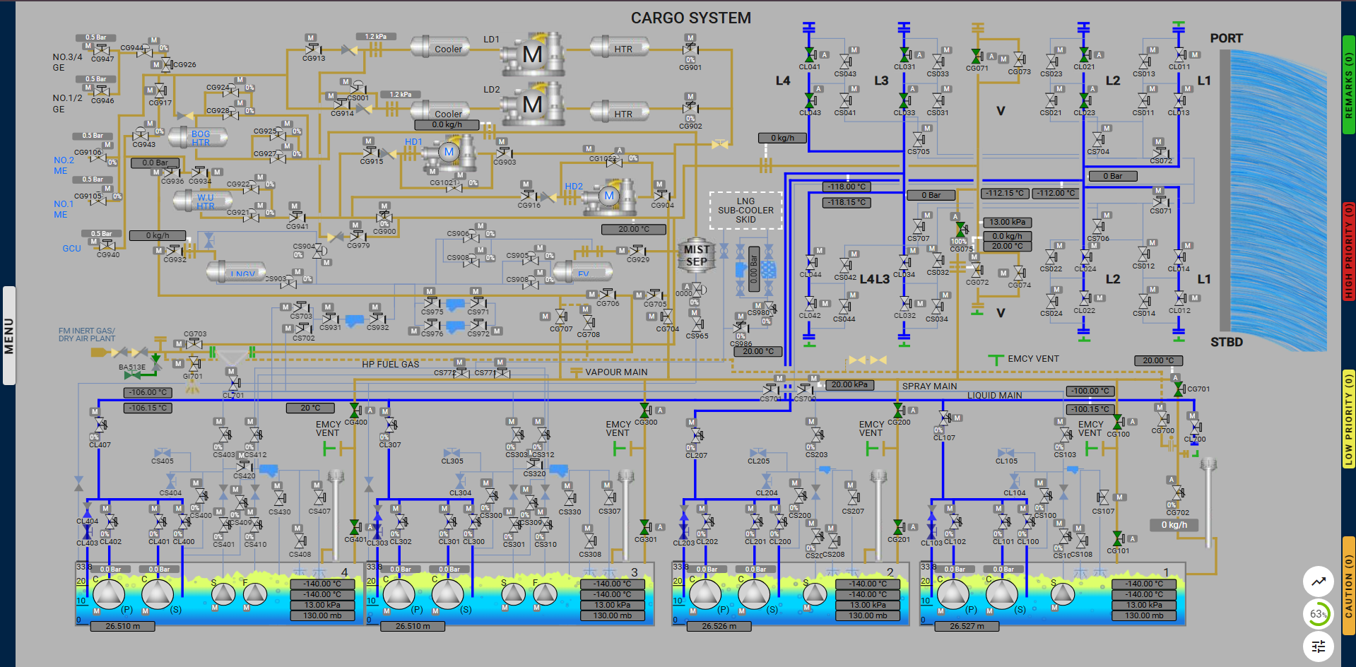
All cargo tanks are simultaneously unloaded using all the cargo pumps into the common liquid line and to the manifolds. It is usual for most terminals to have only three liquid lines and one vapour line connected.

The operation of the cargo pumps can be conducted from the IAS where the operator can select either manual control or auto control.
In manual control, the operator sets the valves to set values before starting each cargo pump. In auto control, the operator sets the valves to auto mode and each cargo pump will start in an auto sequence, when activated by the operator. All the interlocks must be clear to enable the cargo pump to start.

The final stop levels in all tanks should be pre-calculated to determine the amount of heel to be retained. In any event, the cargo pumps can be used to take out most of the LNG without needing to use the stripping/spray pumps.

To avoid unnecessary warming of the pump tower upper section, nozzles are fitted in the cargo pump discharge lines which will spray LNG to continue cooling the upper structure whenever the cargo pumps are running.

Precautions during discharging

The fixed gas detection system must be in operation during discharge;

  • During a normal discharge, only the main cargo pumps should be used. For starting it is preferable to use the sequence provided by IAS as described in Cargo Operation Manual;
  • Before starting the main cargo pumps it is necessary to fill the discharge column with LNG to avoid a pressure surge in the lines;
    When starting the cargo pumps, the discharge valve should be opened fractionally to reduce start load & pressure surge; if necessary, re-circulate liquid carefully to cool deck lines;
  • Most LNG cargo systems require that the discharge valves are opened to a minimum percentage prior to starting, to avoid “hammer” and so that liquid is re-circulated to the tank initially. It may also be necessary to fill the liquid header using a spray pump to reduce start-up “hammer”. The procedures given in the Cargo Operating Manual must be observed;
  • The pump discharge valves should be adjusted to obtain optimum performance as indicated by electrical load, discharge pressure and pump graph;
  • Tank pressures must be monitored and recorded during discharge. As the liquid is pumped out, tank pressures will tend to fall. If there is insufficient boil-off to maintain positive pressures, then vapour must be added to prevent a vacuum – use vapour from shore. Should the vapour return from shore be insufficient to maintain tank pressures, other means of supplying vapour to the tanks, either by using the tank sprayers or the LNG vaporiser, have to be used. If the above fail, discharging rate should be reduced or even stopped. In such cases the gas heater should be prepared and lined up for use well in advance in order to avoid venting cold LNG vapour;
  • Void space/inter-barrier space pressures may also change during discharge. These should also be monitored, recorded and adjusted as required;
  • Levels in all tanks should be monitored and recorded even if they are not being discharged. Any reading that does not change as expected or changes unexpectedly should be investigated;
  • During the discharge period, the ship must be kept on an even keel. If it is required to empty a cargo tank, the ship is trimmed according to terminal maximum draught by the stern to assist in stripping the tank. However, the trim should not exceed 2.80 meters by the stern. For any deviation of the above, head office should be prior informed.
  • When a tank is near empty, one pump should be stopped to avoid excessive turbulence at the tank bottom, which creates disturbance at the suction of both pumps;
  • Pump cavitation should be avoided. The discharge valve should be throttled in when the tank is near empty and before stopping the pump to prevent cavitation, tripping on low current and to maximize the out-turn using spray/ stripping pumps;
  • Cargo pumps (or any other pumps) should never be allowed to run dry as cargo liquid provides lubrication & cooling;
  • On completion of discharge, all liquid lines and cargo arms must be drained & purged inboard with the nitrogen provided by the facilities;
  • The shore line must not be disconnected until it is proven that it is clear of liquid and is also depressurised;
  • All manifold & other isolating valves must be closed before the shore transfer arms are disconnected;
  • The cargo arms must not be disconnected until gas readings obtained from a portable gas instrument are less than 2% Vol CH4 at the manifold vent and drain valves.
  • The vapour arm should be purged with nitrogen from the shore terminal. After confirming that the gas content is less than 2% Vol CH4 at the manifold drain valve, the vapour arm can be disconnected.
  • The pressure that vapour line can be disconnected should be determined taking into account the prevailing conditions at the terminal and the vessel.

Exercise Overview:

  1. Initial Setup:
  • The user must configure the settings on the ESD system and prepare the generators for operation to start the cargo pumps.
  • Configuring the correct settings for the ESD system.
  • Preparing the generators.
  • Starting the custody transfer for official tank aging.
  • Once the correct lineup is complete, the pumps are started one by one to achieve the required discharge rate as specified in the exercise.
  1. Assessment Process:
  • The assessment is carried out in milestones. The user must:
  • Start each pump sequentially.
  • Increase the flow to the required rate, as outlined in the exercise.
  • Ensure the tanks are staggered in such a way that only one tank contains the remaining liquid heel at the end of the process.
  1. Completion Criteria:
  • The exercise is considered complete when the required staggering between the tanks is achieved, and the user has maintained the required flow rate throughout the operation.
  • The user’s performance is evaluated based on their ability to manage the discharging operation, including how they respond to various remarks, alarms, and cautions during the course of the exercise.

When planning an LNG (Liquefied Natural Gas) discharging operation some potential learning objectives for a training program focused on the discharge of LNG (liquefied natural gas):

  • Understanding LNG Properties: Explain the physical and chemical properties of LNG, including its boiling point, density, and flammability.
  • Safety Procedures: Identify and apply safety protocols and emergency response procedures specific to LNG operations.
  • Discharge Process: Describe the step-by-step process of discharging LNG from a tanker to a storage facility.
  • Equipment Familiarization: Demonstrate knowledge of the equipment used during the LNG discharge process, including pumps, hoses, and vapor return systems.
  • Regulatory Compliance: Understand the relevant regulations and industry standards governing LNG discharge operations.
  • Environmental Considerations: Assess the environmental impact of LNG discharge and identify measures to minimize potential risks.
  • Monitoring and Control: Explain the monitoring systems in place to ensure safe and efficient LNG discharge, including temperature and pressure controls.
  • Incident Management: Recognize potential hazards during the LNG discharge process and develop strategies for risk mitigation and incident management.
  • Communication Skills: Demonstrate effective communication and coordination with team members and other stakeholders during the discharge operation.
  • Practical Application: Engage in hands-on training to apply theoretical knowledge in real-world LNG discharge scenarios.

Milestones

  • Learning and Training Phase – Pre-Requisites for the start of operation:
  1. Configure The Correct Setting For The ESD.
  2. Prepare required generators for use.
  3. Ran a custody transfer print-out for official tank gauging.
  4. Connect Manifold Arm Spool Pieces.
  5. Opened required valves for line up.


  • Assessment Phase – Operational flow and Assessment:
  1. Started cargo pumps on all tanks.
  2. Achieved required flow rate to shore.
  3. Staggering achieved for all tanks.
  • The difference of 20cm achieved between CT1 and CT2.
  • The difference of 20cm achieved between CT2 and CT3.
  • The difference of 120cm achieved between CT3 and CT4.

Actions During Exercise:

  1. Deviation from Exercise:
    • After starting or resuming discharging, do not open any non-required valves or close required valves. A caution message will be displayed to undo any incorrect actions. If not corrected, the exercise will be terminated.
  2. High Crossover Pressure:
    • If the crossover pressure reaches 4 bar, the user will be warned to reduce the pump flowrate. If the pressure reaches 5 bar, the user must reduce the crossover pressure within 1 minute. Failure to do so will result in exercise termination.
  3. Not maintaining the required flowrate to shore:
    • If the flow rate is not maintained between 11,500 m³/h and 12,500 m³/h after ramp-up, a caution alarm will be triggered, prompting the user to restore the flow within the required range. If the flow rate remains outside the limits and the alarm escalates to high priority, the exercise will be terminated.
  4. Emergency Shutdown During Operation:
    • During the unloading process, an Emergency Shutdown may be triggered by the terminal.
      In such a case, reset the ESDS system and associated machinery separately, then resume the discharging operation.

Note: When the HD compressor is reset, the surge valve will open, which may result in an incomplete lineup.


Alarms & Remarks

Alarm Condition Alarm Time Alarm Level Alarm Title Alarm Description Actions
Remark Obtained Level Difference Between CT1 and CT2 Obtained a 20 cm difference between CT1 and CT2. Now, the level difference can range between 35 and 45 cm.
Remark Obtained Level Difference Between CT2 and CT3 Obtained a 20 cm difference between CT2 and CT3. Now, the level difference can range between 15 and 25 cm.
Remark Obtained Level Difference Between CT4 and CT3 Obtained a 1.2 m difference between CT4 and CT3. Now, the level difference can range between 1.15 and 1.25m.
caution In-proper Line Up For Discharging Proper line-up has to be done for discharging LNG to the shore.
caution Open Master Valve And Close Return Open master valve CL107/207/307/407 and close return valve CL100/200/300/400 in CT1/2/3/4.
caution Update CTS Report And Setup CTS Report and setup have to be updated before discharging LNG to the shore.
remark Started Unloading Unloading of LNG has started, open master valves of remaining tanks and increase the discharge rate to the required level.
caution Increase Flow Rate Maintain flow rate between -11500 and -12500.
low High Cross Over Pressure High cross-over pressure in liquid line.
caution Liquid Entering The Tank Liquid entering, close master and return valves when pumps are not running.
caution Deviation Detected Deviation from the exercise is detected, undo your last action.


Step By Step Procedure

  • Learning and Training Phase – Pre-Requisites for the start of operation:
  1. Configure the ESD System

Navigate to the ESD System page and follow these steps:

  • Set the Ship/Shore Link Selector switch to USE.
  • Set the Pneumatic Selector switch to BYPASS.
  • Set the ESD Port Selector switch to LOADING.
  • Set the ESD Mode Selector to NORMAL.

Ensure the correct lights and indications are on, confirming the ESD system is ready.


  1. Prepare Generators for Use

Cargo pumps require at least three active generators.

To prepare the generators:

  1. Go to the PMS page via the side navigation bar.
  2. Turn on two of the three generators that are not currently running. (By default, one generator will already be on.)


  1. Run a CTS Report and Activate CTS Status for Official Tank Gauging
  1. Navigate to the CTS Main page using the side navigation.
  2. Set the Ship Mode to Harbour and Filter Mode to Normal.
  3. Fill in the required details in the report data section and select Loading in the CTS report setup.


  1. Connect Manifold Arms
  1. Locate and connect the highlighted manifold arms positioned above the liquid manifold.
  2. Click on each arm to initiate the connection process.


  1. Complete Line-Up by Setting Valves
    a) Set Cargo Liquid Manifold Valves:
      • Open:
        • No.2 Port Cargo Manifold Double Shut Valve: CL023
        • No.3 Port Cargo Manifold Double Shut Valve: CL033
        • No.4 Port Cargo Manifold Double Shut Valve: CL043
        • No.2 Port Cargo Liquid Manifold ESD Valve: CL021
        • No.3 Port Cargo Liquid Manifold ESD Valve: CL031
        • No.4 Port Cargo Liquid Manifold ESD Valve: CL041

b) Set Vapour Line to No.1 Vent Mast:

    • Open:
      • Vapour Line to No.1 Vent Mast Valve: CG701
    • Auto:
      • No.1 Vent Mast Regulating Valve: CG702

c) Set Vapour Manifold Valves:

    • Open:
      • Vapour Line to Manifold Crossover Valve: CG075
    • Port Vapour Manifold ESD Valve: CG071

d) Set Cargo Tank Vapour Valves:

    • Open:
      • No.1 Cargo Tank Vapour Valves: CG100, CG101
      • No.2 Cargo Tank Vapour Valves: CG200, CG201
      • No.3 Cargo Tank Vapour Valves: CG300, CG301
      • No.4 Cargo Tank Vapour Valves: CG400, CG401

Ensure all valves are set to the correct positions for proper line-up. These valves can be opened from different pages in the system.
(Note: Valve CG702 is only available in the Cargo System page.)

  • Assessment Phase – Operational flow and Assessment:

Important Note: When the HD compressor is reset, the surge valve will open, which may result in an incomplete lineup.

  1. Commence LNG Discharge to Shore by Running a Cargo Pump
  1. Navigate to the specific tank page by either clicking the pump icon on the unloading page or via the side navigation.
  2. Ensure the interlock conditions are met to start the pump.
  3. Once the interlock conditions are met, open the pump options by clicking the specific pump icon to start the pump.
    • Note: After starting a pump, you cannot start another pump for the next 5 minutes.


  1. Increase and Maintain the Required Flowrate to Shore

After 55 minutes of unloading, the user will be alerted to increase and maintain the flowrate between 11,500 m³/h and 12,500 m³/h.

  • If the flowrate is not increased within 5 minutes, a low-priority alarm will trigger.
  • If the flowrate is still not adjusted after another 5 minutes, a high-priority alarm will trigger.
  • If the flowrate is not adjusted within 1 minute after the high-priority alarm, the exercise will be terminated.
  1. Staggering Achieved for All Tanks

Achieve the required tank level differences:

  • 8A: Achieve a 20cm difference between CT1 and CT2.
  • 8B: Achieve a 20cm difference between CT2 and CT3.
  • 8C: Achieve a 120cm difference between CT3 and CT4.

To achieve this, the user must adjust the pump discharge valves while monitoring the crossover pressure. If the crossover pressure is not maintained within the acceptable range, the exercise will be terminated.

Once the required tank differences are achieved, the exercise is completed.

Proper line up discharging ramp up and staggering: