This operation is carried out after the liquid line cool-down has been completed. The user is tasked with performing the initial two hours of the LNG loading operation. During this operation, the user ramps up the flow from the shore and loads LNG into the cargo tanks in stages. The goal is to increase the flow from 0 to 10,000 m³ per hour while ensuring that the tank levels are staggered so that all tanks do not reach their full capacity at the same time.
LNG is loaded via the loading manifolds to the liquid header and then to each tank filling valve. The boil-off and displaced vapour leave each tank via the vapour domes to the vapour header. The vapour is initially free-flowed to shore via the vapour crossover manifold and, as tank pressure rises, one compressor is brought into operation to increase the gas flow to shore and limit the vapour main and hence cargo tanks’ pressure.
De-ballasting is undertaken at the same time as cargo loading, and the de-ballasting sequence is arranged to keep the vessel within the required limits of draught, trim, stress, and stability. If necessary, the flow of nitrogen to the inter-barrier spaces is increased to maintain a positive pressure in these spaces during the completion of cool-down and the start of loading. This is often achieved by increasing the pressure in the inter-barrier spaces before starting the operation.
The cofferdam heating system is put into operation well in advance and before arrival at the terminal; e.g. when low atmospheric temperature on arrival at the port system must be set in operation well in advance. The open sea system is always in operation, to maintain steady temperatures at cofferdams and dome spaces.
On completion of loading, the liquid header and other liquid pipes are drained usually to the aft cargo tank. The liquid remaining in the inclined part of the liquid manifolds is pushed in board using N2 pressure from shore and the loading arms are then purged and disconnected.
Preparations for Loading
Loading is commenced after the cool-down of the cargo piping with one of the shore pumps. This can be done by opening the ESD and double shut valves, allowing liquid to flow directly into the main liquid lines or by opening the ESD valve and crossing over into the smaller spray line and then back to the liquid line inboard of the double shut valve. The latter system has the advantage of restricting the flow of liquid from the shore as it passes into the smaller-diameter spray line. In either case, the liquid flows initially to the end tanks (1 and 4) and then to all tanks.
Once the ship and shore pipelines have cooled down (about 90 minutes), open all tank filling valves and commence loading at the agreed rate. Loading rates are usually increased (ramped up) in agreed increments to the maximum loading rate in about one hour or as per the pump-up plan.
As the loading rate increases, it is important to monitor the evolution of the tank pressures and to start one or two HD compressors in order to limit the pressure in the tanks. If the compressors are unable to cope with the volume of boil-off and displaced gas, it will be necessary to reduce the loading rate.
During the time of cooling down of the piping and the start of loading, it is important to patrol the whole deck area to monitor for all potential cargo leaks. All leaks, even the smallest one, must be corrected immediately even if this requires slowing down or even stopping the loading.
Precautions during the early stages of loading
The initial loading rate should be at the terminal minimum rate or at a rate, which is within the capabilities of the vessel’s vapour control equipment. The rate can then be increased gradually to the maximum agreed rate where the tank pressures can be maintained steady at a working level sufficiently below the relief valve setting;
The boil-off and displaced vapour are initially free-flowed to shore via the vapour crossover manifold and, as tank pressure rises, one HD compressor is brought into operation to increase the gas flow to shore. Under these conditions, the loading rate is governed by the rate at which the terminal can handle the vapour;
In the early stages of loading, the cargo tanks and/or the incoming cargo liquid may be warm and generate vapour in excess of the vapour return line capacity. A close watch must be kept on cargo tank pressures;
The loading rate must be reduced in good time before nearing the relief valve set pressures;
LNG High Duty Compressors should be immediately available with enough electrical power available to ensure immediate starting. HD compressors should be cooled down and the lube oil warmed up prior to normal use.
If reducing the rate or the use of High Duty Compressors does not control the pressure rise, the loading must be stopped immediately and the terminal notified. In some occasions when the shore/ terminal cannot control the BOG return, then and after agreement Gas burning shall be commenced.
Loading Operation
The terminal will connect the shore loading and vapor arms to the vessel’s manifold. The ship-to-shore Emergency Shutdown (ESD) cable will be connected and the integrity confirmed. The loading and vapour arms and connections to the vessel will be leak tested to the agreed pressure and checked for leaks. A warm ESD and cold ESD test will be carried out complying with the agreed procedure.
LNG is loaded via the liquid crossover manifolds to the cargo liquid line and then to each cargo tank branch and filling valves. The boil-off and displaced vapour leave each cargo tank via the gas domes to the cargo vapour line. The vapour is initially free-flowed to the terminal via the vapour crossover manifold. As the tank pressure rises, one or both of the HD compressors are brought into operation to increase the gas flow to the terminal and limit the cargo tank pressure. Deballasting is undertaken at the same time as cargo loading and the deballasting sequence is arranged to keep the vessel within the required limits of draught, trim, stress and stability. Deballasting should be completed before the end of loading.
The nitrogen pressurisation system for the insulation spaces would normally be in automatic operation and lined-up to supply the additional nitrogen necessary to compensate for the contraction from cooling the tanks.
The cofferdam heating system should be in operation and working correctly. On completion of loading, the cargo liquid line and other liquid lines are drained to the No.4 cargo tank. The liquid remaining in the inclined part of the liquid manifolds is pushed inboard using nitrogen pressure from the terminal, and the shore arms are then purged and disconnected.
Allowance must be made when topping off the No.4 tank for cargo arms and lines draining back to this tank to prevent overfilling the tank.
It is important to remember:
The exercise begins with the setup of necessary systems and machinery, including Starting the required equipment. Configuring various systems. Lining up the valves to direct LNG into the cargo tanks.
Learning Objectives for the Exercise
Participants will be able to effectively demonstrate the process of loading cargo tanks on LNG ships, understanding the necessary safety protocols, operational procedures, and the significance of maintaining safe and efficient loading operations.
Key Components:
Assessment Criteria:
By achieving this objective, participants will gain the knowledge and skills necessary for safely and efficiently loading cargo tanks on LNG ships, ensuring successful and secure LNG operations.
Actions taken during the exercise
Failure Conditions for Crossover Pressure and Instantaneous Rate
Emergency Shut down during operation
During the loading process, a leak may be detected in the liquid line L2. In such a case, the user should navigate to the ESDS System page and activate the ESD Manual Push Button to trigger an emergency shutdown. After resetting the system, the user can proceed with resuming the loading process.
| Alarm Condition | Alarm Time | Alarm Level | Alarm Title | Alarm Description |
| After Starting Loading | During The Ramp up every 6th minute this alarm will be thrown | remark | New ship rate 1000m³/h available | Increase ship rate to 1000m³/h. |
| Whenever the tank’s instantaneous rate reaches above 4000m3/h | caution | High Pressure In Manifold Lines | High pressure in liquid manifold line, open or increase the filling valve percentage. | |
| When pressure reaches 14kpa | caution | Start The HD Compressor | High pressure inside the tanks, start the HD compressor. | |
| When pressure reaches 14.5kpa | caution | Increase HD Compressor Veins | High pressure inside the tanks, increase the HD compressor veins to maintain pressure. | |
| When pressure reaches 15kpa | caution | Start Another HD Compressor | Start another HD compressor, reduce the veins of HD Compressor 1 before starting another HD compressor. | |
| When pressure reaches 15.5kpa | caution | Increase The Veins Of Both The HD Compressors | High pressure inside the tanks, increase the veins of both HD compressors to maintain pressure. | |
| When an unnecessary valve is opened. | caution | Deviation Detected | Deviation from the exercise is detected, undo your last action. | |
| When difference obtained | Remark | Obtained Level Difference Between CT1 and CT2 | Obtained a 40 cm difference between CT1 and CT2. Now, the level difference can range between 35 and 45 cm. | |
| When difference obtained | Remark | Obtained Level Difference Between CT2 and CT4 | Obtained a 20 cm difference between CT2 and CT4. Now, the level difference can range between 15 and 25 cm. | |
| When difference obtained | Remark | Obtained Level Difference Between CT4 and CT3 | Obtained a 20 cm difference between CT4 and CT3. Now, the level difference can range between 15 and 25 cm. | |
| Crossover Pressure > 4.5 bar | Low/High | High Cross Over Pressure | High cross over pressure in liquid line, increase tank filling valve opening. |
Step By Step Procedure
To ensure the ESD system is ready:
Check that the correct lights and indications are ON before moving to the next step.
Milestone 1 (M1)
After ensuring that the valves are correctly set as per the above list, the lineup will be complete.
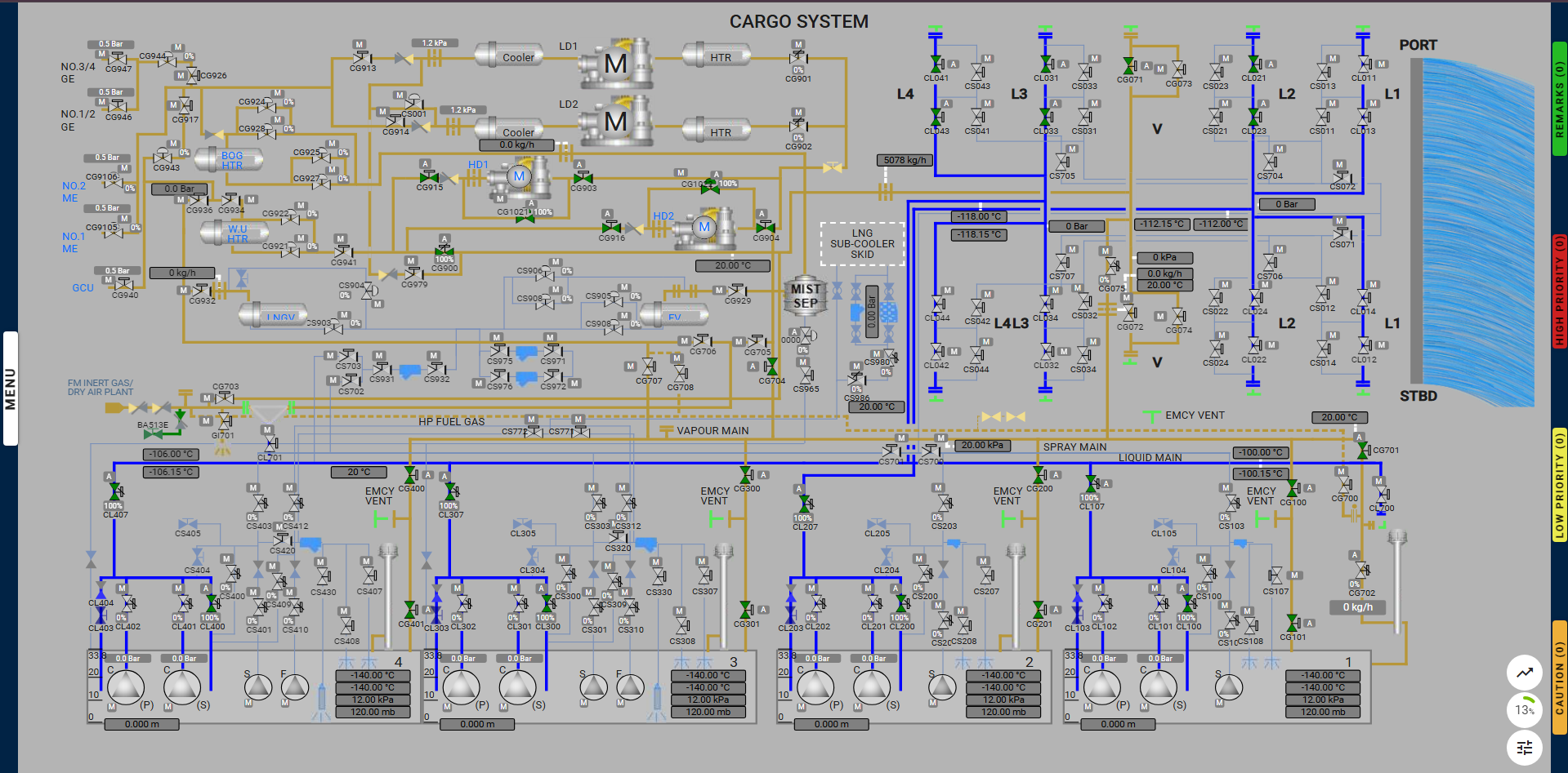
Note: Valve CG702 is only available on the Cargo System page and Cargo Tank No.1.
The user should adjust the filling valves to achieve the required level differences between the cargo tanks. Each tank level should be staggered to make the topping-off process easier.