The purpose of the initial cooling down is to place the cargo tanks in a suitable cold condition for loading LNG. The initial cooling down must be gradually undertaken to reduce the cargo tanks’ temperature down to cryogenic temperature to:
The initial cooling down normally follows immediately on from the gassing-up operation and is achieved using LNG supplied from the terminal. This is delivered to the spray line and is sprayed into each cargo tank, which will cool down the cargo tank and surrounding insulation. A large amount of vapour will be generated and this is returned to the terminal by using the High Duty (HD) compressors.
The rate of cooling down the cargo tanks is pre-calculated and this, along with the terminal’s ability to receive the returning vapours, are the time limiting factors. The cooling down rate with the amount of LNG required is presented to the vessel in a tabulated format.
To control the spray rate according to the cargo tank pressure, the spray lines are adjusted by the operator to achieve the cooling down schedule. The spray line pressure supplied from terminal is to the vessel’s request.
Initial starting up
On initial start-up, the requested pressure should be low in order to permit gradual cooling down of the cargo tank and structures. Once the spray line and rail and line are cooled, shown by frosting on the spray line into each cargo tank, the pressure can be increased to full pressure.
During cooling down, nitrogen flow to the IBS will significantly increase. It is essential that the rate of cooling down is controlled so that it remains within the limits of the nitrogen system to maintain the IBS pressure.
Cooling down of the cargo tanks is considered complete when the temperature sensors in each tank indicate the target average temperature. When this average temperature has been reached, and the Custody Transfer System (CTS) registers the presence of liquid, bulk loading can begin.
Vapour generated during the cooling down of the cargo tanks is returned to the terminal via the HD compressors and the vapour manifold.
Once the cooling down is complete and loading has commenced, the cargo tank membrane will be at or near to the cargo temperature, but it will take some hours to establish fully cooled down temperature gradients through the insulation. Consequently, boil-off from the cargo will be higher than normal during the first 3-4 days after loading to fully cool all of the cargo tank insulation to the loaded voyage operating temperature.
During the cooling down of the cargo tanks, cooling down the cargo lines can be undertaken. The purpose of cooling down lines is to slowly reduce the line temperature to a cryogenic level to avoid thermal shock, prior to loading LNG.
Once the cooling down of the cargo tanks is nearing completion, cooling down the lines can start, this includes the liquid manifold crossovers, cargo liquid line and filling lines to be used for loading.
It is achieved by the terminal supply of LNG being partially diverted from the spray line into the manifold crossover valves to the cool down valves on each manifold and through the double-shut valves, crossover lines and along the liquid lines to the cargo tank filling lines and valves.
As LNG slowly fills the lines the temperature probes at the manifold crossover and forward and aft sections of the liquid line should be carefully monitored for temperature drop and subsequent frosting.
Filling valves to the cargo tanks should be adjusted accordingly to ensure that there is a minimum flow through the valves to permit excess vapor out and allow the liquid line to fill and cool.
This exercise focuses on the operation of cooling down cargo tanks onboard an LNG carrier. The exercise begins with all tanks in a “gassed-up” condition, where the atmosphere inside the tanks is fully filled with LNG vapor.
Exercise Overview:
Liquid LNG is introduced from the shore and directed toward the cargo tanks via spray lines, which contain spray nozzles inside the tanks. The LNG is sprayed into the tanks, gradually lowering the temperature. The goal is to reach a loading temperature of -130°C inside all cargo tanks. The vapor pressure inside the tanks is released to the shore using the high-duty compressor (HD compressor) onboard.
Prepare the high-duty compressor and generators for operation. Connect the manifold arms and hoses (referred to as “spool pieces”). Ensure the correct valves are lined up to direct the LNG into the tanks via the spray lines.
The assessment begins once the lineup is complete and all equipment is ready for operation. The LNG flow is started from the shore, and the user must achieve a temperature of -130°C inside the tanks. Throughout the assessment, the user must maintain the correct LNG flow in order to achieve the temperature drop in the requisite time period and respond to any rising tank pressure by operating the HD compressor appropriately.
The exercise is considered complete when the target temperature of -130°C is reached inside all cargo tanks within the stipulated time. The user is assessed based on their response to various remarks, cautions, and alarms presented during the exercise.
Learning Objectives for the Exercise
Participants will be able to effectively demonstrate the process of cooling down cargo tanks on LNG ships, understanding the necessary safety protocols, operational procedures, and the importance of achieving the required temperatures for safe LNG loading.
Key Components:
Understanding Cooling Down:
Operational Procedures:
Monitoring and Verification:
Practical Demonstration:
Assessment Criteria:
By achieving this objective, participants will gain the knowledge and skills necessary for safely and efficiently cooling down cargo tanks on LNG ships, ensuring operational readiness for LNG loading.
| Alarm Condition | Alarm Time | Alarm Level | Alarm Title | Alarm Description | Action |
| When prerequisite milestones for starting the cooldown are completed. | Before Starting Cooldown | Remark | Begin the cooldown process with a low flow rate. | Begin the cooldown with a low flow of 25 m³/h. | |
| Tank Middle Temp <= 5°C | When particular tank middle sensor temperature reaches 5°C | Remark | Reduce Master Valve Opening In CT 1,2,3,4 | Reduce the master valve opening to at least 25% For CT1 and 50% For CT2,CT3,CT4. | |
| Valve not closed to required percentage, after receiving the remark | After 1 minute of receiving the remark alarm | Caution | Reduce Master Valve Opening In CT 1,2,3,4 | Reduce the master valve opening to at least 25% For CT1 and 50% For CT2,CT3,CT4. | |
| Tank Middle Temp <= 0°C | When particular tank middle sensor temperature reaches 0°C | Remark | Close One Nozzle In CT 1,2,3,4. | Close one spray nozzle in cargo tank 1 and continue cooldown. | |
| One Nozzle Not Closed After Receiving the Remark(And Action Not Taken). | 5 minutes after receiving the remark | Low Priority | Close One Nozzle In CT 1,2,3,4. | Close one spray nozzle in cargo tank 1 and continue cooldown. | |
| One Nozzle Not Closed After Receiving the low priority (And Action Not Taken). | 5 minutes after receiving the low priority | High Priority | Close One Nozzle In CT 1,2,3,4. | Close one spray nozzle in cargo tank 1 and continue cooldown. | |
| whenever temperature drop exceeds the max level. | Whenever the drop is more than -17°C during stage 1 or 11°C during stage 2. | Caution | High Temperature drop in CT1,2,3,4. | High temperature drop in CT1,2,3,4, Adjust master valve CS103,203,303,403 or reduce the flow from shore. | |
| Cargo Tank Pressure >= 14kpa | Caution | Start HD Compressor | High pressure inside the tanks, start the hd compressor. | ||
| Cargo Tank Pressure >= 14.5 Kpa | Caution | Increase HD Compressor Veins | High pressure inside the tanks,increase the hd compressor veins to maintain pressure. | ||
| Cargo Tank Pressure >= 15Kpa | Caution | Start Another HD Compressor | Start another hd compressor, reduce the veins of HD Compressor 1 before starting another hd compressor. | ||
| Cargo Tank Pressure 15.5 Kpa | Caution | Increase The Veins Of Both The HD Compressors | High pressure inside the tanks, increase the veins of both hd compressors to maintain pressure. |
Step By Step Procedure
Prepare Both HD Compressors and Required Generators for Use
Connect Manifold Arm Spool Piece
Complete the Line-Up by Following the Required Steps
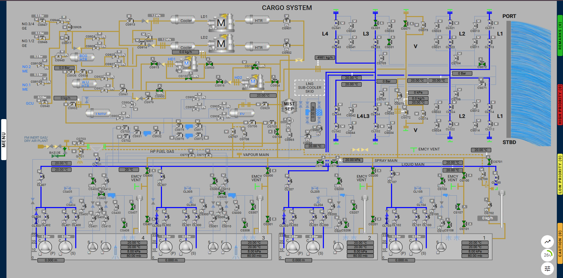
| Position | Description | Valve |
| Open | No.1 cargo tank vapour valves | CG100, CG101 |
| Open | No.2 cargo tank vapour valves | CG200, CG201 |
| Open | No.3 cargo tank vapour valves | CG300, CG301 |
| Open | No.4 cargo tank vapour valves | CG400, CG401 |
| Position | Description | Valve |
| Open | Vapour line to No.1 vent mast valve | CG701 |
| Close & Auto | No.1 vent mast regulating valve | CG702 |
| Position | Description | Valve |
| Open | No.3 port cooling down valve | CS031 |
| Open | Spray line crossover isolation valve | CS072 |
| Open | Spray line isolation valves | CS700, CS701 |
| Position | Description | Valve |
| Open | No.1 cargo tank spray master valve | CS103 |
| Open | No.1 cargo tank spray rail valves | CS107, CS108 |
| Open | No.2 cargo tank spray master valve | CS203 |
| Open | No.2 cargo tank spray rail valves | CS207, CS208 |
| Open | No.3 cargo tank spray master valve | CS303 |
| Open | No.3 cargo tank spray rail valves | CS307, CS308 |
| Open | No.4 cargo tank spray master valve | CS403 |
| Open | No.4 cargo tank spray rail valves | CS407, CS408 |
| Open | No.3 cargo tank spray block valve | CS320 |
| Open | No.4 cargo tank spray block valve | CS420 |
| Position | Description | Valve |
| Open | No.1 HD compressor inlet valve | CG903 |
| Open & Auto | No.1 HD compressor surge valve | CG1021 |
| Open | No.1 HD compressor outlet valve | CG915 |
| Open | No.2 HD compressor inlet valve | CG904 |
| Open & Auto | No.2 HD compressor surge valve | CG1022 |
| Open | No.2 HD compressor outlet valve | CG916 |
| Open | Compressor line valve to vapour manifold | CG900 |
| Position | Description | Valve |
| Open | Vapour line valve to HD compressors | CG704 |
| Open | Port vapour manifold ESD valve | CG071 |
| Position | Description | Valve |
| Open | No.3 port cargo liquid manifold ESD valve | CL031 |
Note: The user must ensure that the above valves are set correctly across the various pages for proper line-up.
Note: Valve CG702 is only available in the Cargo System page.
Starting the Cooldown Process
HD Compressor Requirements
Achieve Required Temperatures Inside the Tanks
Completion of Exercise